1. Enter the part origin parameters (G54-G59)

1) The MODE knob is set to "EDIT";

2) Press MENU OF SET to enter the parameter setting page;

3) Use the PAGE DOWN or UP ARROW keys to toggle between the No1 and No3 coordinate system pages and the No4 to No6 coordinate system pages (Figure 1).

1

Figure 1 No1~No6 respectively correspond to G54~G59

4) Use the CURSOR down or up arrow keys to select the coordinate system;

5) Press the numeric keys to enter the address word (X/Y/Z) and value to the input field;

6) Press the INPUT key to enter the contents of the input field to the specified position.

2. Enter tool compensation parameters

1) Input radius compensation parameters

1 MODE knob is set at "EDIT";

2 Press MENU OF SET to enter the parameter setting page;

3 Use PAGE DOWN or UP ARROW to select the radius compensation parameter page, as shown in Figure 2;

1

Figure 2 Radius compensation parameter page

4 Use the CURSOR: down or up arrow keys to select the compensation parameter number;

5 Enter the compensation value into the input field;

6 Press the INPUT key to enter the compensation value in the middle of the input field to the specified position.

2) Input length compensation parameter

1 MODE knob is set in EDIT;

2 Press MENU OF SET key to enter the parameter setting page;

3 Use the PAGE down or up arrow key to select the length compensation parameter page, as shown in Figure 3;

1

Figure 3 Length compensation parameter page

4 Use the CURSOR down or up arrow keys to select the compensation parameter number;

5 Enter the compensation value into the input field. Refer to the "Input Data" operation for the method.

6 Press the INPUT key to enter the compensation value in the middle of the input field to the specified position.

3) Position display

Press the POS button to switch to the position display page, as shown in Figure 4. There are three ways to display the position, use PAGE: down or up arrow keys or soft key to switch.

1 Part Coordinate System (absolute coordinate system) Position: Displays the position of the tool location in the current part coordinate system.

2 Relative coordinate system position: Displays the relative position that the operator presets to zero.

3 Comprehensive display: At the same time, the position of the tool location in the following coordinate system is displayed at the same time

1

Figure 4 Location display page

4) Relative coordinate system (RELATIVE) is set to zero

Enter the RELATIVE display page in the relative coordinate system; press:

1

v1

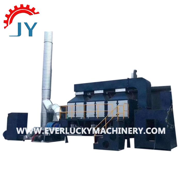
VOCs Catalytic Combustion System consists of four(or three) activated carbon adsorption tanks and a catalytic combustion chamber. The exhaust gas in the production line is collected and sent to the gas collection box, and then the exhaust gas is sent to the filter to filter out the dust in the exhaust gas, thereby preventing the activated carbon micropores from being blocked. The filtered exhaust gas enters the adsorption chamber, and the activated carbon adsorbs the VOCs in the exhaust gas. When the activated carbon adsorber is close to saturation, the saturated activated carbon adsorber is desorbed and desorbed by the hot gas flow, and the organic matter is desorbed from the activated carbon. During the desorption process, the organic waste gas has been concentrated, and the concentration is increased by several tens of times to more than 2000 mg/m3. The concentrated exhaust gas is sent to the catalytic combustion device, and finally decomposed into CO 2 and H 2 O and discharged. After the analytical desorption is completed, the activated carbon adsorber enters the standby state. When the other activated carbon adsorbers are close to saturation, the system automatically switches back, and the saturated activated carbon adsorber is analytically desorbed, so that the cycle works. The finally cleaned clean gas is discharged into the atmosphere by the main exhaust fan

VOC Gas Treatment Equipment

Voc Treatment System,Voc Treatment Equipment,Vocs Catalytic Combustion,Voc Gas Treatment Equipment

Botou Ever Lucky Environmental Protection Machinery Co., LTD , https://www.dustcontrolling.com

Posted on