Scenery. 1 Asynchronous motor-power electronic converter power generation system application background Compared with synchronous motor, DC motor, and wound-type asynchronous motor, cage-type asynchronous motor has the advantages of simple structure, firmness, low cost, convenient maintenance and high power density. As a reversible motor, the asynchronous motor can be used in power generation, and the asynchronous motor in the power grid absorbs the inductive reactive power from the power grid to excite, and in the super synchronous operation, it is in the power generation state. The cage asynchronous generators of the independent power supply operation described in this paper have previously used the method of the motor output and the capacitor to achieve the excitation, but when the prime mover speed changes or the load impedance changes, it is difficult to maintain the constant voltage and frequency. These shortcomings make it asynchronous to use asynchronous motors as generators. In recent years, due to the emphasis on the use of renewable energy, wind power generation, small hydropower generation, and tidal power generation have been greatly developed. Due to its outstanding advantages, cage asynchronous motors are more and more widely used in power generation systems for renewable energy. The key to the application of asynchronous generators is to solve the problem of voltage regulation and frequency modulation. Before the 1980s, the main non-power electronics solutions were reported in the newspapers. Since the late 1980s, due to the rapid development of power electronics technology, it has become possible to use power electronics technology to control asynchronous generators and solve the problem of voltage regulation and frequency modulation. Since the 1990s, there have been many patent reports based on cage-type asynchronous generator-power electronic converter power generation system, and it is mainly applied to wind power and small hydropower generation. At present, due to the concept of all-electric aircraft and all-electric tanks, there are many electrical and electronic equipments for aircrafts and tanks, and the requirements for equipment dual-function power supply systems for starting/generating power are proposed. It can be used for electric operation before power generation, starting the engine, and then turning to power generation after the engine is running. This new power system is of great value for in-depth research. In a starter/power generation system composed of a combination of a power electronic device and an asynchronous motor, it is necessary to control the transfer energy bidirectionally, and different control strategies are adopted for power generation and electric power, respectively. The electric control technology has been relatively mature, and the key is the control of power generation operation. The high-speed flywheel energy storage system is also a research hotspot. The storage and release of energy must be completed by the motor. In fact, it is an electric/power generation system, and the asynchronous motor is competitive. Asynchronous generator-power electronic converter power generation system can be divided into two types according to the connection relationship between motor, converter and load. One type is parallel between converter, asynchronous generator and load, and the load is directly output from the motor. The end receives electrical energy and the converter provides the reactive power required by the asynchronous generator. The other type is asynchronous generator, converter and load series. The electric energy generated by the generator is transmitted to the load through the converter. The converter can control the active and reactive power of the asynchronous generator. These two types of connections have their own characteristics and have their own suitable occasions. The parallel type converter is mainly used to provide reactive power, so the capacity is small, and the AC power can be directly output from the generator. The inverter is not required, and the system has high operating efficiency, but it is not suitable for the occasion where the range of the prime mover has a large variation range. The series type is suitable for the occasion where the range of the prime mover's speed varies greatly. The dynamic characteristics of the system are good, and it is suitable to establish a high-voltage DC system with dual functions of starting power generation. 2 Cage Asynchronous Motor - Power Electronic Converter Power Generation System Technical Status The power electronic converter used to control the asynchronous generator is actually the same as the DC-AC three-phase inverter. It is a three-phase bridge structure. According to the previous two basic classifications, the basic characteristics of several representative structural forms and their control strategies are introduced respectively. 2.1 Parallel Structure Parallel Structure Asynchronous Generator A power converter in a converter power generation system is mainly used to provide a parallel generator working principle and working modal diagram for asynchronous generators. As a result, the requirements for constant frequency of the source to the source are not too high, and an asynchronous generator-converter power generation system with a substantially constant frequency scheme is used. Because it can pass, accurately adjust the excitation and reactive power input to the asynchronous generator to adjust the structure of the asynchronous generator system to apply the magnetic field oriented vector control, reactive reactive excitation, specific to a certain application system, the connection relationship and control of the circuit The strategies have their own characteristics, which can be divided into the converter's complete constant frequency mode of operation and the basic constant frequency mode of operation. The constant frequency operation is taken as an example. As shown, the input power of the prime mover in a separate power supply system is varied. The frequency of the sinusoidal modulation signal of the converter is fixed to the DC side of the 60 Hz converter as the battery pack. The system has three modes of operation: 1 When the output power of the generator is equal to the power required by the load, the converter does not transmit active power and only provides the reactive power required by the generator and the load. 2 When the output power of the generator is less than the power consumed by the load, the converter operates in the inverter state, the battery is discharged, and the inverter supplies power to the load. 3 When the output power of the generator is greater than the power consumed by the load, the converter operates in a rectified state, absorbing excess power from the generator to charge the battery. The system actually operates the asynchronous generator in parallel with the inverter, and requires more batteries to form a battery pack to reserve and release electrical energy. The common point of this type of system reported is that the operating frequency is completely determined by the converter of the fixed modulation frequency, and then the constant output voltage of the generator is controlled in different ways, so that the system can operate under constant voltage and constant frequency, allowing The generator speed varies within a certain range, but the prime mover's speed cannot be lower than the synchronous speed. Another commonality is that the dynamic characteristics of the system are not ideal, and the recovery time of the sudden load is longer. The output voltage of the motor is set to make the dynamic performance better. A novel solid-state voltage regulator scheme for a self-excited asynchronous generator is presented. The scheme decomposes the reactive component and the active component required by the inverter control voltage based on the asynchronous generator terminal voltage, and adjusts the output voltage of the generator by accurately adjusting the two components. In contrast, the field oriented vector control precisely controls the field current of the asynchronous generator. The research results of the application of magnetic field oriented vector control in asynchronous generators by Lyra et al. are published. The system structure is as shown in the figure, and the stator field oriented vector control is adopted. The amplitude and phase angle of the stator flux vector are obtained by the Luenberger flux linkage observation algorithm; the excitation component of a given current is obtained by PI deviation from the deviation of the given flux amplitude and the observed value of the flux linkage; the active component of a given current The deviation between the given value of the DC voltage on the DC side of the converter and the measured value is obtained by PI adjustment. The computer simulation analysis of the rotor flux linkage vector control strategy of asynchronous generator is introduced. The advantages and disadvantages of the two orientation modes of the field oriented control of the field current of the asynchronous generator in the form of a parallel structure are the same as those of the asynchronous motor vector control. Since the AC load is directly connected to the output of the asynchronous generator, the frequency offset of the output voltage must meet the requirements of the consumer, so the speed of the prime mover cannot be varied over a wide range. A solution is proposed to output a constant DC voltage after the generator output AC is rectified by a diode rectifier bridge to supply power to the DC load or the inverter. Another solution is to form an asynchronous generator-converter power generation system in a series configuration. 22 Asynchronous generator-inverter power generation system with series structure and serial structure is suitable for applications where the range of prime mover speed is large. It is used in wind power generation systems. 111. Introducing the connection topology in series power generation system Basically the same, but the control strategy adopted can be divided into two different categories: one uses V/f control technology and the other uses vector control technology. The following two types of control strategies are summarized. The control strategy of the V/f control strategy is taken as an example. The working principle is as shown in the figure. The V/f control strategy is relatively simple. The control algorithm can be realized by a general microprocessor, but the dynamic response of the system is poor. From the point of view, the field-oriented vector control technology of the asynchronous generator adopts the stator field orientation mode or the rotor field orientation mode. The following examples provide an overview of the two vector control techniques. The energy conversion system of the asynchronous motor connected by a bidirectional converter, wherein the rotor field oriented control strategy of the asynchronous generator is as shown. The system detects the rotor speed and the stator current, and the rotor flux linkage observation algorithm obtains the amplitude and phase angle of the rotor flux linkage. In the rotating coordinate system, the difference between the given value and the observed value of the flux linkage determined according to the magnitude of the rotational speed is adjusted by PI to obtain the excitation component of the stator current, and the system outputs the DC voltage (converter DC side voltage) given value and actual detection. The deviation of the value is adjusted by PI to obtain a part of the active component of the stator current, and the other part is estimated by the power required to load the inverter and the motor driven by it (qe). The sum of these two parts is the active current of the stator current. The component is then subjected to coordinate rotation transformation and two-phase to three-phase transformation to obtain a given value of the stator current of the asynchronous generator. The PWM control signal of the IGBT three-phase bridge is generated by current tracking. The scheme of stator field oriented control for asynchronous generators is introduced, and the application patent in wind power generation is obtained. Due to the high rotational speed of the asynchronous generator, the Luenbeiger observation algorithm of the stator flux linkage in the stationary coordinate system is actually a simple integration algorithm. The parameters of the motor only use the stator resistance, and the change of the stator resistance has little effect on the flux linkage observation. . The rotor field orientation accuracy is greatly affected by the rotor parameters (resistance and inductance), which will seriously affect the dynamic performance of the system. Since the asynchronous generator does not operate at low speed, the stator field oriented control strategy is superior to the rotor field oriented control strategy. The structural block diagram of the stator field oriented control is basically the same as the rotor field oriented control except for the flux observer. The output voltage of an asynchronous generator-converter power generation system that controls the series structure is stable, and it is actually determined only by whether the active power emitted by the system at the moment can be balanced with the power consumed. The reason why the vector control dynamic performance is good is to decouple the excitation component and the torque component of the asynchronous generator current. Under the field oriented control, the generator torque has a simple proportional relationship with the given value. For the self-excited voltage-generating power generation problem of the cage-type asynchronous generator-converter power generation system, the self-excitation voltage of the capacitor at the end of the generator can be used; or the pre-charged DC voltage of the battery can be connected to the DC-side capacitor of the power electronic converter. The converter provides reactive self-excitation. In controlling the generator excitation, the proper given amplitude (or excitation current component) and the appropriate torque reference (or active current component) of the flux linkage must be determined as a function of the DC voltage, especially in In the case where the precharge voltage is low, self-excitation will not be achieved otherwise. How to use the residual magnetic voltage of the asynchronous generator like the self-excitation of the capacitor, it is worthwhile to further study the self-excited voltage of the asynchronous generator by controlling the converter. 3 Conclusion Asynchronous generator rotor field oriented control strategy converter power generation system will be very competitive, and now it is gradually becoming a renewable energy generation system. In the new starter power generation dual function power system, the cage type asynchronous generator is combined. Power electronics has become a research hotspot in the world. Power electronics technology has a large number of technologies that can be used for reference in the electric operation control of asynchronous motors. How to make the dynamic and static characteristics of the asynchronous generator-power electronic converter power generation system more perfect for the characteristics of variable-speed power generation operation, and it is worthwhile to study in terms of system model, control strategy and circuit topology.
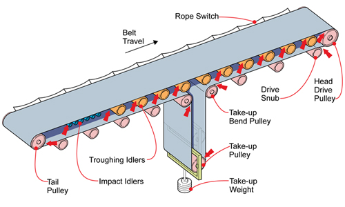
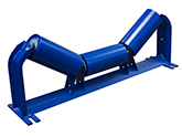
Troughing idler, which is the most common idlers used on belt conveyor, is mounted on the carrying side, used for conveying bulk materials. Generally it consists of 3 rollers in equal length. The two outer rollers are inclined upward and the middle one is horizontal. The inclined degree can be 30°,35°and 45°, some can be up to 60° in suspended type. There are two basic types: standard type and ahead inclined type. The latter can also be present all through the conveyor to prevent the belt from sideslip.
A Troughing Idler is comprised of a central idler roll, which has a fixed width, and two or more wing idlers located on each side of the central idler roll. The wing idlers can be adjusted up or down to change the toughing angle, which affects the depth of the trough created by the conveyor belt as it moves.
The troughing idlers comprise a centre idler roll of a defined width, and 'wing' idlers on either side of the centre roll. Unlike the centre, horizontal roll, the wing idlers are cranked up to an angle known as the troughing angle. This troughing angle ensures that the carrying belt maintains the same cross-sectional area throughout the carrying strand, so that the load-bearing capacity of a particular conveyor belt is the same along the conveyors' full length. In so doing, material loaded to the maximum capacity at the loading point will not fall off of the belt en-route.
Diameter idler mm
Length (tube) mm
Bearing
89
180.190.200.235.240.250.275.280.305.215.350.375.380.455.465.600.750.950.1150
204
108
190.200.240.250.305.315.360.375.380.455.465.525.530.600.700.750.790.800.950.1150.1400.1600
6204 6205 6305 6306
133
305.375.380.455.465.525.530.600.670.700.750.790.800.900.950.1000.1100.1150.1400.1600.1800.2000.2200
6205 6305 6306
159
375.380.455.465.525.530.600.700.750.790.800.900.1000.1050.1100.1120.1150.1250.1400.1500.1600.1700.1800.2000.2200.2500.2800.3000.3150.
6305 6306 6308
194
2200.2500.2800.3000.3150.3350
6308 6310
217
600.640.1050.1120.1600.1700.3150.3350.
6308 6310
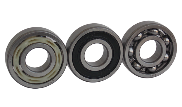
Troughing idlers usually deep groove ball Bearing For Conveyor Idler roller.
To be the first class, to do the best quality, to make users satisfied, to ensure customers relieved, are our enterprise purposes. Welcome bearing dealers` and Conveyor Idler manufacturers contact from all over the world, and become our partner.
Troughing Idler Troughing Idler ,Trough Idler,Conveyor Troughing Idler Shandong Xinkaite Bearing Co., Ltd. , https://www.conveyorbearing.com

