When manufacturing automobile gearboxes, in order to obtain a proper center distance, negative displacement gears are sometimes used. If the gear negative displacement is too large, the transition curve interference is likely to occur when meshing with the mating gear, and such interference is sometimes difficult to verify accurately. The following takes the gearbox gear produced by our factory as an example to introduce how to check the interference of the gear transition curve and how to avoid interference.

1
Figure 1 The original hob normal tooth profile

1 The relevant parameters of the gear transition curve interference check gear 1 are: the normal module mn=2.5mm, the number of teeth Z1=34, the normal pressure angle an=22.5°, and the pitch circle spiral angle b=30°27′. The displacement coefficient xn1=-0.8762, the diameter of the tip circle da1=100.22-0.20mm, the root circle diameter df1=85.46-0.10-0.05mm, and the effective involute starting circle diameter dnf1=89.3mm. The related parameters of the gear 2 paired with the gear 1 are: the number of teeth Z2 = 37, the normal displacement coefficient xn2 = -1.1509, the diameter of the tip circle da2 = 107.8 - 0.20 mm, and the center distance A = 97 mm. The shape of the gear transition curve is related to the parameters of the gear cutter. The normal tooth profile of the original shave hob of the processing gear 1 is shown in Fig. 1 (0.07 mm for shaving remaining). First, the calculation method is used to check the gear transition curve interference. The end face engagement angle a12' of the gears 1 and 2 is cosa12'= mn (Z1+Z2)cosat2Acosb (1) where: at——the gear minute end face pressure angle, and tanat=tanau/cosb (2) the related parameters Values ​​substituted into (1) and (2) can be calculated as a12'=16°56'04". If the gear does not interfere with the transition curve, the condition 2Asina12'-(da22-db22)1⁄2≥(dnf12-db12)1⁄2 should be satisfied. (3) Where: db1, db2 - are the base circle diameters of gears 1, 2 respectively, and db1 = mnZ1cosat 2cosb (4) db2 = mnZ2cosat cosb (5) Substituting the relevant parameter values ​​into equation (3), can be calculated 8.894 8.78.722, obviously meets the condition that the gear does not interfere with the transition curve.In order to ensure the reliability of the interference check, the gear pair is then subjected to the transition curve interference check using the drawing method. The tooth profile is converted into the face tooth profile. According to the principle of gear development, the hobbing process is simulated with AutoCAD software (the shaved head can be removed before the simulation), and the face tooth profile of gear 1 is obtained (see curve 1 in Fig. 2a); Draw the tooth profile of the gear 2. According to the gear meshing process, the tooth profile of the gear 2 is tangent to the tooth profile of the gear 1 at the pitch circle, and then the gear 2 is wound. Pure rolling wheel 1 at the pitch circle, to obtain the desired shape cogging gear meshing with the gear 1 2 (curve 2 in Figure 2a).

1
(a)

1
(b)

Fig. 2 Interference check diagram of the original transition curve The interference situation of the gear transition curve is analyzed according to Fig. 2b: It is obvious that the gear will not interfere with the transition curve in region I. This is consistent with the above calculation results; however, the gear 1 can be observed in region II. If it is too narrow, it will interfere with the transition curve of the gear 2, which is consistent with the actual phenomenon that the gear 1 is squeezed there. If a calculation method is used to perform a transition curve interference check on the tooth profile, the calculation process will be very complicated. The reason for the occurrence of transition curve interference is that the gear negative displacement is too large. Therefore, unless the center distance is limited, excessive negative displacement should be avoided. 2 Measures to Avoid Interference of Gear Transition Curves To avoid interference of gear transition curves, the following measures can be taken: Reduce the pressure angle of the hob to make the top of the hob wider, in addition to processing a wider gear slot, The durability of the hob can be improved. When the gear strength and the degree of overlap are allowed, the diameter of the tip circle of the mating gear can be appropriately reduced. In the case where the strength of the gear allows, the diameter of the root circle of the gear can be appropriately reduced. In this example, the normal pressure angle of the hob can be reduced from an = 22.5° to an = 20°. The improved hob normal tooth profile is shown in Figure 3. Under the condition that the diameter of gear 2's tip circle is constant, using AutoCAD software to simulate the gear meshing state of the improved hob (see Figure 4), it is found that the gear pair does not interfere with the transition curve, which proves that the improved scheme is effective. In actual production, in order to ensure that no interference of the transition curve occurs, the diameter of the tip circle of the mating gear 2 is reduced from da2=107.8-0.20 mm to da2=107-0.20 mm.

1
Figure 3 Improved hob normal tooth profile

1
Fig. 4 Improved Interference Interference Check Chart

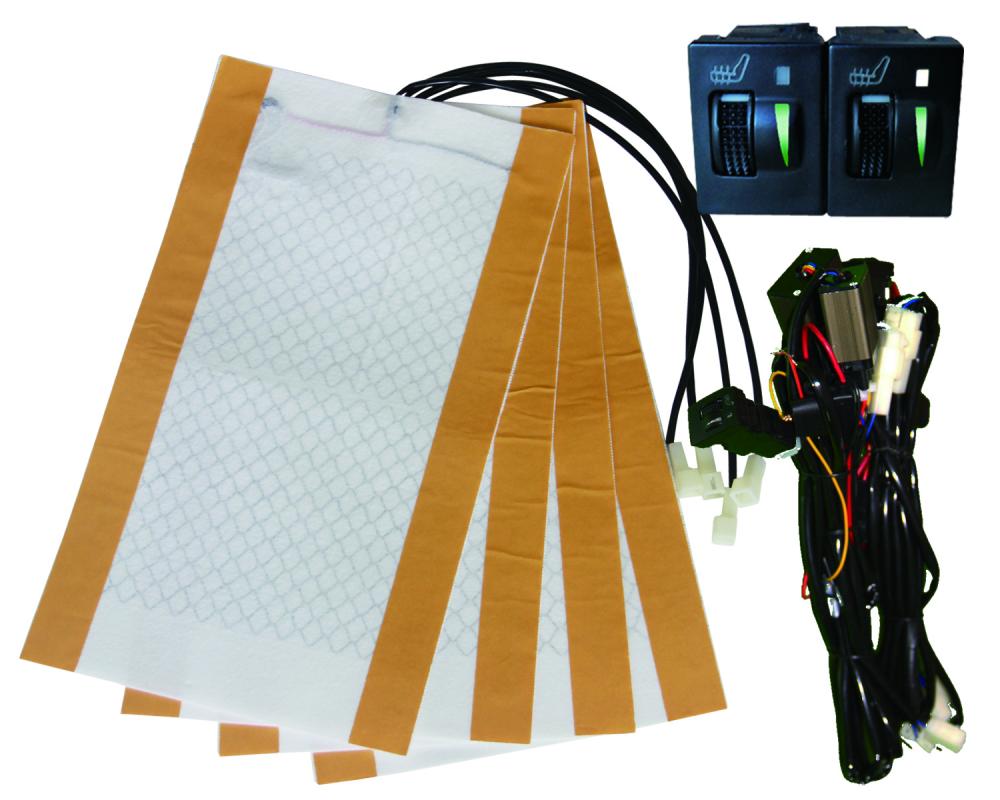
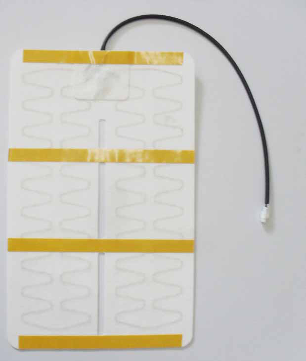
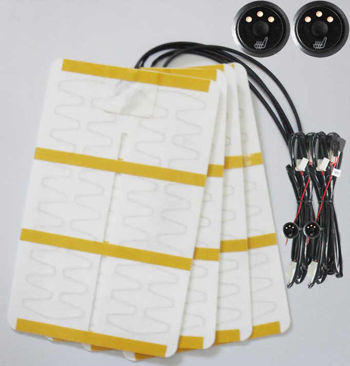
Heated Seat In Car

Whether it is during the cold winters or hot summer days, this is a versatile car seat that will suit you best. It has been equipped with both heating and cooling systems so that it provides quality services. Apart from this, it also provides a vibrating massage for a good feeling when driving. Apart from this, the heated car seat is very safe thanks to the overheat protection thermostat system.

It also has up to dive levels of heating areas that will keep the body at the required temperature. It heats faster in just three minutes; hence very efficient. It comes with remote control for easy operation.Toyota 5 Gear Switch789Alloy Gasket78999 789

Seat Heated,Heated Seat In Car,Car Seat Warmer,Heated Seats Car Seats

JiLin Province Debang Auto Electric Co.,Ltd. , https://www.dbheatedpads.com

Posted on